| |
|
| Browse | Ask | Answer | Search | Join/Login |
|

|
||||
|
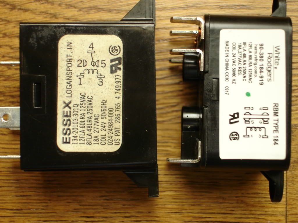
Looks like 5 and 4 are normally closed according to your wiring diagram then 4 and 2 activate upon 24 volt power.
Try putting a jumper between 4 and 5 also attaching the original wires to the respective terminals. Then attach the number 2 wire to the number 2 terminal. Here is what should happen. When the new relay is not activated tabs 4 and 5 will be together just like the old relay. When 24 volt power is applied terminals 2 and 4 will be activated droping terminal 5 out. You might test this using 24 volts to activate and unactivate the relay and your meter to make sure I am correct. NOTE no changes necessary for the 24 volt feed/activation wires. Just use the same numbers. |
||||
|
||||
|
I have 5 wires.. So should I wire as follows: #1 wire to #1 terminal #3 wire to #3 terminal #4 wire to #4 terminal #5 wire to #5 terminal #2 wire to #2 terminal Jumper between 4 & 5 terminals I would have thought to jumper terminals 4 & 6 to complete the circuit for normally closed... |
||||
|
||||
|
You can jump between 4 and 5 or 4 and 6. They are actually the same terminal since they are jumped internally as long as the relay is not energized with 24 volts.
I stated terminal 5 so as not to confuse the issue by adding another terminal number. |
||||
|
||||
|
NO do not jump the coil wires those are 24 volt and it will burn something out since that will cause a direct short in the low volt system.
Disconnect wire on tab 5 or 6 depending upon which tab you used (see other discussion on this) then Jump 4 and 2 and see what happens. This way you are making direct contact for voltage to the motor and the motor should run. Put wires back where they were Then Then try disconnecting 2 and jumper 4 and 5 and see what happens NOTE: this is the W/R page for this relay.. http://www.white-rodgers.com/wrdhom/..._06_pg0115.pdf I hope during this entire process you have identified all the wires that are being used on this relay. If they get mixed up you will have to trace back and that will take all the fun out of it. |
||||
|
||||
|
Okay guys.. Im back home. Had to go out of town for a short trip.. Here's the test results from Saturday: Installed the new relay and wired per instructions. All I get is a constant hum from the fan with thermostat is in off position. Jumpered relay wires 2 & 4 to test the fan. The fan comes on. So, I reinstalled old relay. It gives me the same results. Now, my fan only comes on with jumpered wires 2 & 4. What changed? Don't make any sense as I haven't changed anything else.. What should I test next? |
||||
|
||||
|
If 2 and 4 when jumpered works the fan then something is wrong with this picture.
When the unit is in the A/C mode check for 24 volts on pin 1 and 3. There should be 24 volts there and the relay should pull in to activate the fan. If 24 volts is not present then another device is holding the 24 volts from getting to the relay. The only other possibility is that we have the relay wired backwards but I really do not think so. |
||||
|
||||

Agreed, something is wrong with this picture... First, I have always on fan. Now I have a always hum and instead of the fan on... But before I go up in the attic to check for 24v on pins 1 & 3, I just completed a little test that sort of did the same thing... I changed the fan setting on thermostat from auto to ON always. Turn on power at air handler and the fan came on.. But I like your test better... I post again in 30 min.. |
||||
|
||||
|
Set the volt meter for the scale that will read the 24 volt circuit.
Then disconnect both wires from the relay. Then attach the meter to the two wires and see if you have 24 volts when the system is in the A/C mode. If not try the fan on mode on the thermostat and test again. I never trust the frame ground for testing. Test using the wires only. They must be disconnected from the relay for the test. If you do not have 24 volts there you are going to have to trace back to find the 24 volts and the reason it is not getting to the relay. |
||||
|
||||
|
The relay should be activated in the A/C mode.
See below http://customer.honeywell.com/techli...0s/69-0392.pdf See section 5 When C1 makes it triggers the fan relay through the on off fan switch in the off position. Now I am starting to believe there could be a problem with the wiring at the thermostat. Why it worked for a few days is anyone's guess. |
||||
|
||||
|
Okay.. Last night, I noticed that the new relay was melting at terminal #3. The plastic started to deform. So, I put back the original relay and tested the heat cycle (as it was cool last night here). Everything worked fine except for the hum when fan was off. The fan went off during the system off stages and the fan came on with the heat pump during the heating stage. Everything works as programmed. Changed the Thermostat to AC this morning and the old symptoms returned: Fan hum always and the Heat Pump/fan goes on & off as called by the thermostat. Then I set the Thermostat to OFF but the fan continues to hum.. This is strange. Killed the power and came to work.. :( Im now thinking that it is the Thermostat wiring too. The new relay wiring is also suspect but Im ordering a new original York relay just to be safe. Also still wondering about the high transformer reading. Thermostat wiring connections: Old = New R = R and Rc Jumpered Y = Y G = G O = O/B W = Aux B = C X = E . |
||||
| Question Tools | Search this Question |


Add your answer here.
Check out some similar questions!
My inside ac fan will not turn off.
I am replacing some old can lights with some new ones - the two cans aer on a three way switch and the wire from the switch to the old cans was a 12-3 - the way the cans were wired had the red wire twisted together while the white and black wires fed the lights - after the second canister light...
My furnace blower will not turn off iwas reading on this site where to tap on relay to see if it is stuck.where is the relay? Does it look like a transformer?
My airconditioner was working fine last night,today it won't even turn on,I checked the breaker box still nothing, can someone help answer
My A/C unit won't kick on. I have a mercury dial thermostate. I just changed the filter. I put my dial to 70 and nothing. I had 2# of Freon added to it in 2005. Shouldn't it still be OK?
View more questions Search

|
